Final Project
Design
The concept of my final project was essentially an interactive narrative. The Yiddish poem by A. Lutsky I used in Input Devices had been adapted, as I discovered in the Harvard archives, for a theatrical recitation by Joseph Buloff and A. Trommer. (You can find all this material on another site of mine: archive.yiddish.nu.) I hoped to take this English story version of the poem and print it in real time, and what it prints depends on the user's interaction with peripheral items.
Coming up with the peripheral items required some thorough brainstorming. Some, I decided, would directly involve aspects of this particular story, others would apply to narrative structures and storytelling in general. I came up with the following:
- Slide potentiometer: as a fast-forward/rewind device. The idea was that the storyteller (microcontroller) might or might not abide by these commands (i.e., "Stop trying to fastforward, be patient!"). I ended up using one that had a motor attached, so it can be set by the user and the microcontroller.
- Toggle switch: this would simply be a distraction. Opening or closing the switch would simply irritate the storyteller and perhaps end the story prematurely.
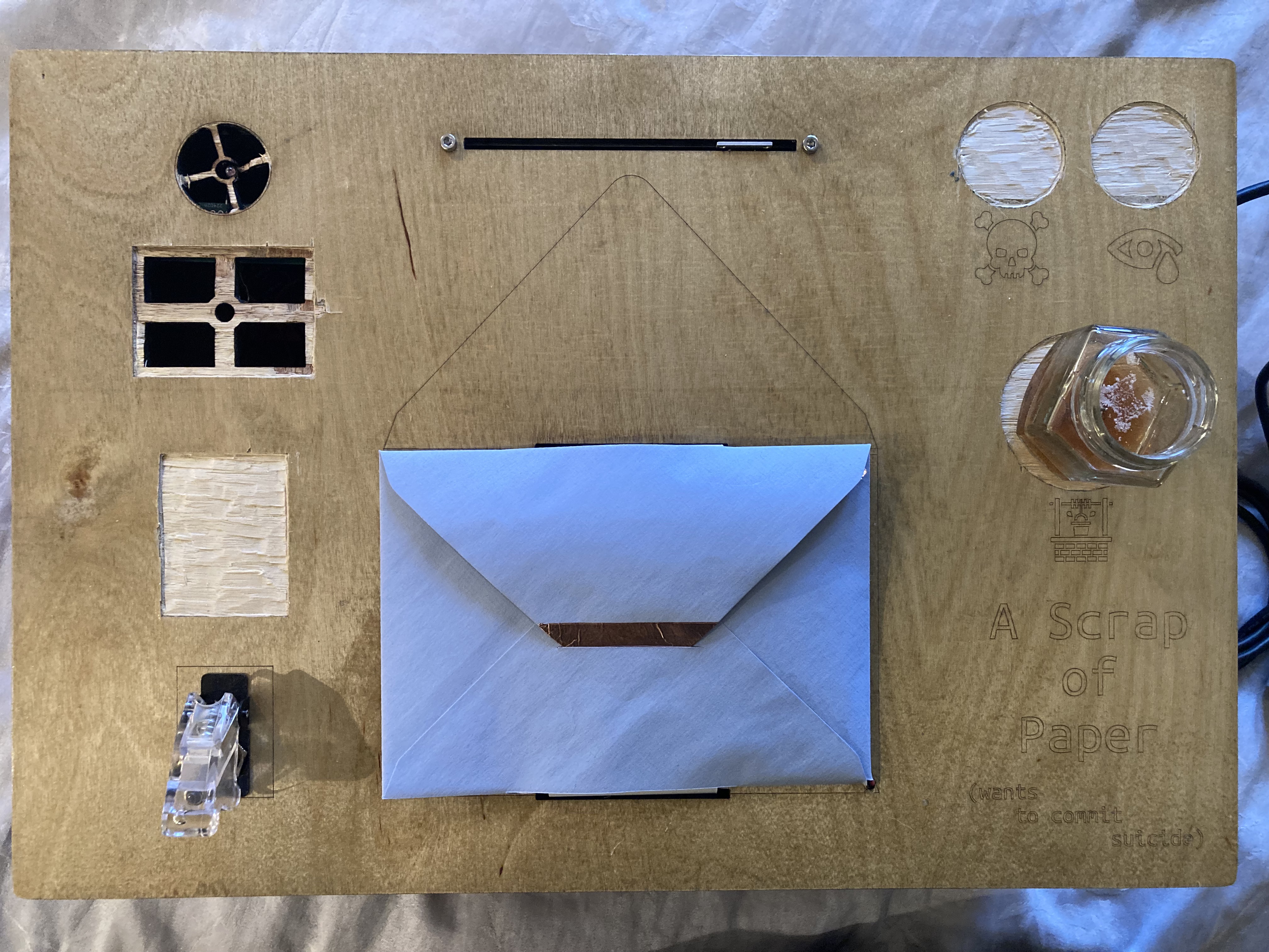
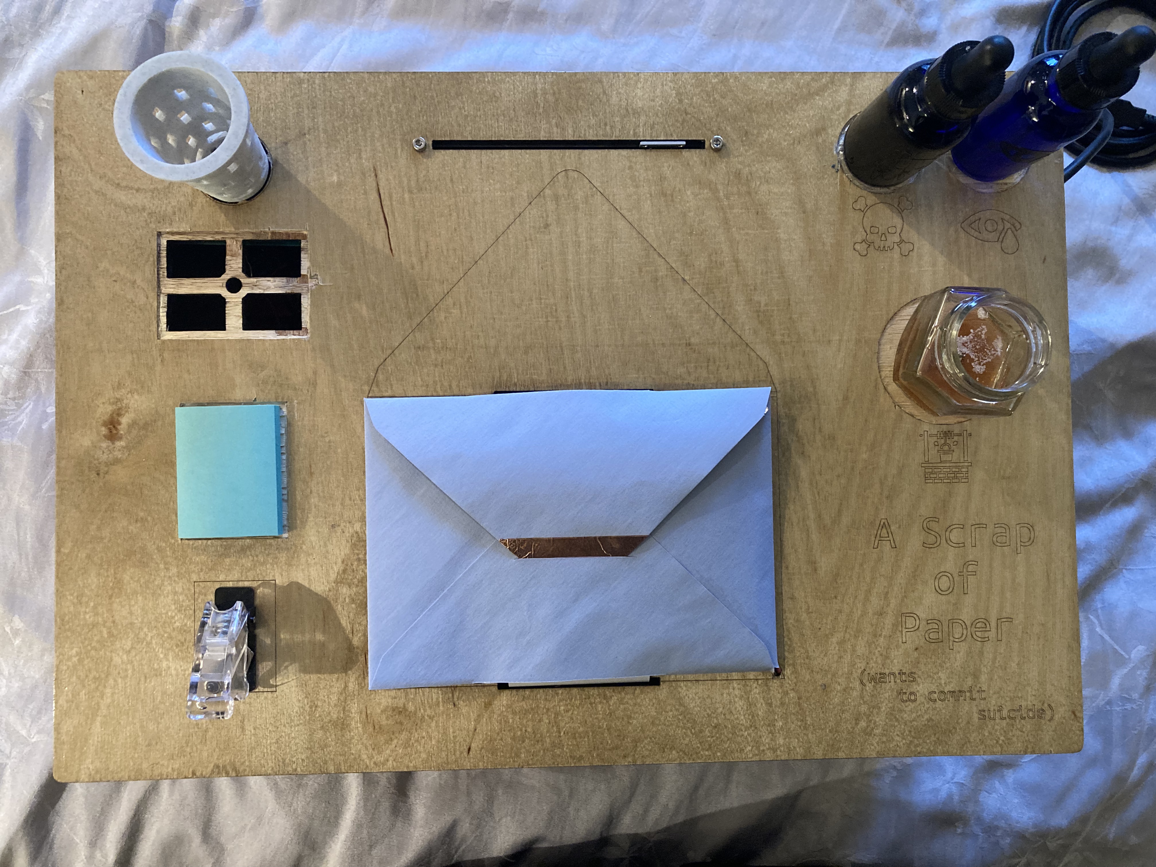
- Water sensor: the story involves a woman who threatens to kill herself and a lover boy who is meant to cry (but doesn't) upon receiving a love letter from her. Here the user can affect the outcome or sequence of events of the story by supplying "poison" or "tears" to the "well" (a container with a water quality sensor fixed to the bottom, see CNC). The solutions contain different concentrations of salt, making it quite easy to determine what is being added to the well.
- Two phototransistors: these would be placed under a "trash bin" and a "shoebox." The user would be supplied with little post-its representing letters. Should they put them in the trash (i.e., throw the letter out) or in the shoebox (i.e., save it for posterity), the storyline is effected. I had originally planned to have a fan installed under these items (hence why the lasercut gameboard has cutouts on the top left). When the paper befriends the wind, as it does in the story, I wanted the papers in both receptacles to be blown out. The fan was not powerful enough so I removed it.
- A capacitive touch sensor: a simple circuit wired to copper adhesive on the envelope lip and closure. This detects when the envelope is opened and closed. This is, in essence, turning on the screen or opening the book.
Cutting
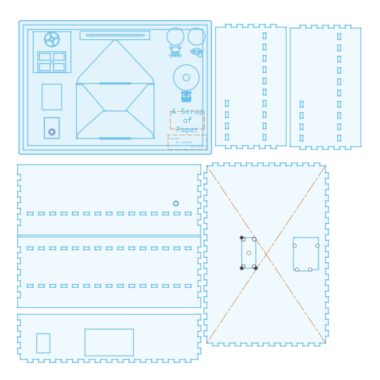
With the gameboard in mind, I made the design to be laser cut and voila:
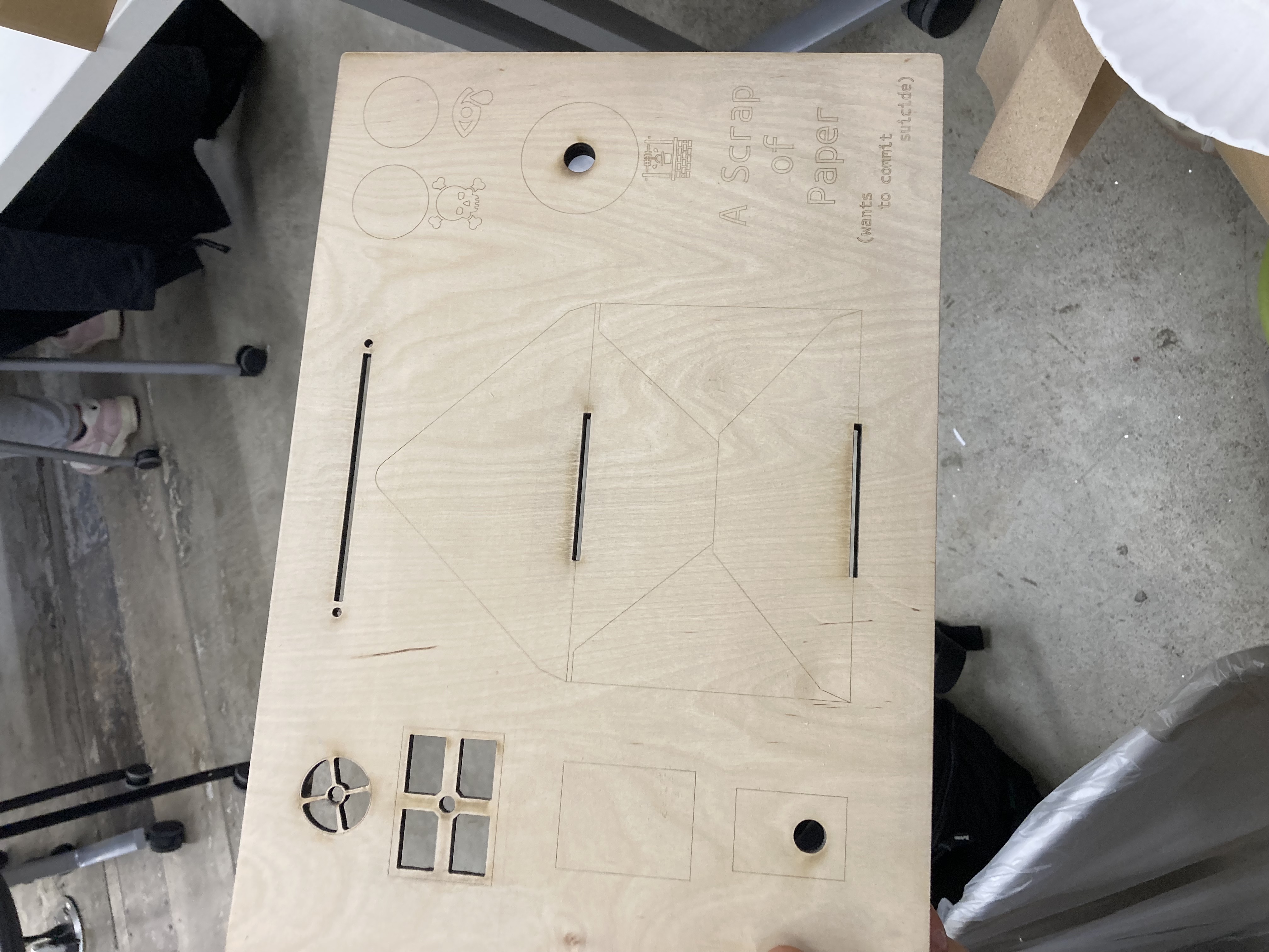
It looked really nice and I ended up putting a finish on the board game and chiselling out the places for the items (since CNC was ripping the plywood to shreds)—thanks Ollie for the idea. Had I known about the "hatch" fill mode in Rhino I might have used that instead actually... The skull, tear, and well icons that I engraved in the wood and cut on the vinyl cutter for the dropper bottles are from the Noun Project. See the links.
I made the inside of the box one-and-a-half layered. Half of a top layer about 10mm from the top to hold the mini thermal printer. A full level underneath that I assumed would be plenty of space for the electronics and the receipt wrapper. More on that later.
Box Body DXF Gameboard DXF
NOTE: The groove on the underside of the gameboard ended up being a few mm off from the box edge resulting in an imperfect fit.
Printing
Since the story was to be printed in realtime by a receipt printer "under the hood," fed through the gameboard, through the envelope, back out the envelope, back through the gameboard, something had to be pulling it along and gathering the paper. I designed a mount for a continuous rotation servo (which I assumed correctly could rotate slowly and steadily) and a corresponding spindle the size of the thermal paper. This would be fixed to the main internal level of the box, at about center. When the printer would run, so woud the servo. These were 3D printed and work surprisingly well.
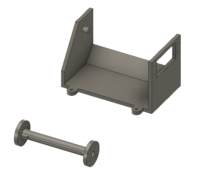
Spindle Mount STL Spindle Mount GCODE Spindle STL Spindle GCODE
The trashcan you can see in the Design section I also designed and 3D printed. The design was to let light through to the phototransistor and let air through from the ultimately absent fan. Note that the spot for the shoebox in that same picture is empty. I never made it because I never got those sensors to work and I would have made it of cardstock by hand and had no need to plan for it in advance.
Trashcan GCODEMaterials
Besides the box materials I ultimately used the following items and components:
- TDS meter (and the sample code they provide).
- 2.1mm power jack.
- Mini thermal receipt printer and Adafruit's Arduino library.
- Motorized Slide Potentiometer
- L9110 Motor Driver
- Continuous Rotation Servo
- This somewhat convienient Proto shield for Arduino
- 9V 2 Amp power supply
- 2 Dropper bottles and shorter wider glass jar
- Envelope and copper adhesive
- 2 phototransistors
- A bunch of resistors (value in circuit diagram)
- Lots of wire
Assembling
It is at this stage that I made the most plentiful and significant mistakes the result of premature decisions and permanent implementations. Before wiring anything, I looked over the datasheets for all the components I planned on using and made a circuit diagram I am sure is technically flawed, but was very helpful for organizing and visualizing. It is missing the envelope capacitive touch however, which is just a wire to digital out and a wire to analog in.
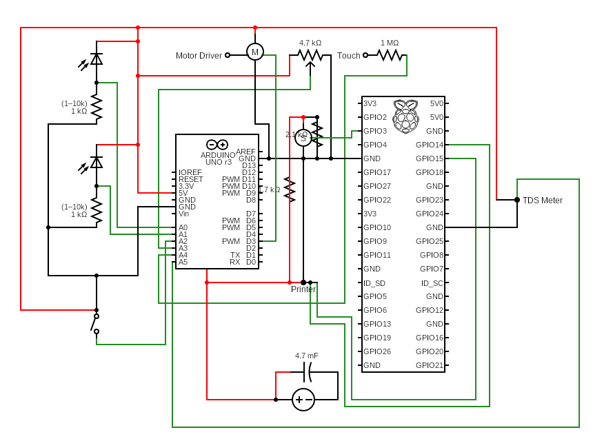
As you can see I had planned on using both an Arduino and a Raspberry Pi (Zero W). The intention was to let Arduino harvest the analog inputs from all the sensors, report this all routinely to the pi via serial, and have the pi control the printer and possibly the servo. I wanted this setup for three reasons: (1) I knew Arduino memory would likely not be able to store all of the story's text; (2) I am very comfortable with text manipulation in python and not so much in arduino/c++; and (3) I had thought, if I have time, why not incorporate OpenAI's nice python API for narrative options or even user scoldings.
This all seemed so simple to me, that I simply assumed it would all work. The only thing I tested before soldering everything was the power supply. I wanted a unified power supply for: the arduino, the printer, and the servo. (The pi I thought I would power via usb-in from the arduino. I don't think this actually works. You can power pi zero from the bus of a laptop to the pi's usb-in——as in, not power-in——but the arduino doesn't seem to output the same amount.) Via barrel jack, the arduino needs over 7.5 V. The printer needs between 5-9V at 1.5 amp and the servo, according to the datasheet, works best at 5V. So I ran six ground and power wires to one barrel jack mounted to the rear of the box. Each power cable pair had its own endpiece (barrel, JST, and just wires). My wall outlet supply was 9V 2amp and so had to be reduced for the servo. I made a voltage divider. I tested all of this with a voltage meter and it worked.
Except for two things. (1) The Arduino on LED would not turn on with any of the various male barrel endings I tried. I tested them. They were providing power. I even plugged it in to the Arduino and tested the terminals and solder joints—they were reading 9V. But no light. If however I took the power cable ends (without the male barrel end) and made direct contact with the solder joints of the female barrel jack on the arduino——LED is on! I puzzled with this for probably hours (I thought maybe something involving the third pin that checks if anything is inserted) until I just decided to solder the power cables directly to these joints. This caused no issues down the road.
(2)The servo despite claiming it runs best on a seperate 5V supply, would hum but not move. I fixed a little bit of wire to skip over all the resistors on the voltage divider to see if it would run on 9V, or die, and it worked. So voltage divider was useless.
The box was easily assembled. As I soldered the electronics I fit or mounted them in the box. I was quickly starting to realize that it was getting crowded in there. But time was ticking... I had to move on...
Programming
Goodbye Pi: Adafruit has an archived python library for communicating with the thermal printer. I had tested their arduino library and assumed the python one would work just as smoothly. But I couldn't communicate with it. I did not try very long, probably due to delirious fatigue. I got rid of the pi from the setup. I have a new take now. See the Result section for that.
I quickly had all the sensor's smoothly reporting their readings on the arduino, except for the two phototransistors, which I must have wired incorrectly, but for the life of me I can't figure out how or where. The idea was to have the arduino update these readings at regular intervals in between which it would print the appropriate segments of the story (i.e., the segments in response to the sensor readings).
But as I began to involve the text things started to mess up. First, the predicted memory problem arose. I temporarily "solved this" by simply eliminating any logical option of getting beyond the first segment. As in, if you flick the toggle, story teller gets annoyed and stops. Fastforward and the storyteller will start anew cause you're impatient, etc. The second problem I did not see the root of until now, a few days after our final project fair, on reinvestigating the issue with some sleep in my pocket. The String() functions I was using were causing the arduino to actually skip over chunks of code. You can see the latest malfunctioning (but better) code here. I didn't think this possible without causing some kind of compilation error, but sure enough it is. So here are two videos (inside and outside) of a partially function Lutski's Scrap-O-Paper. The goal is to put an end to reading-fatigue and the tiresome pursuit of the author's intent, as exhibited in this other video. I will make a proper trailer when it's better runnning.
Result
Despite many failures, I think I can say I came close to something beautiful and functioning. I am very much intent on getting this thing not only working but working magnificently, with actual narrative possibilities. My mistakes can be outlined as follows:
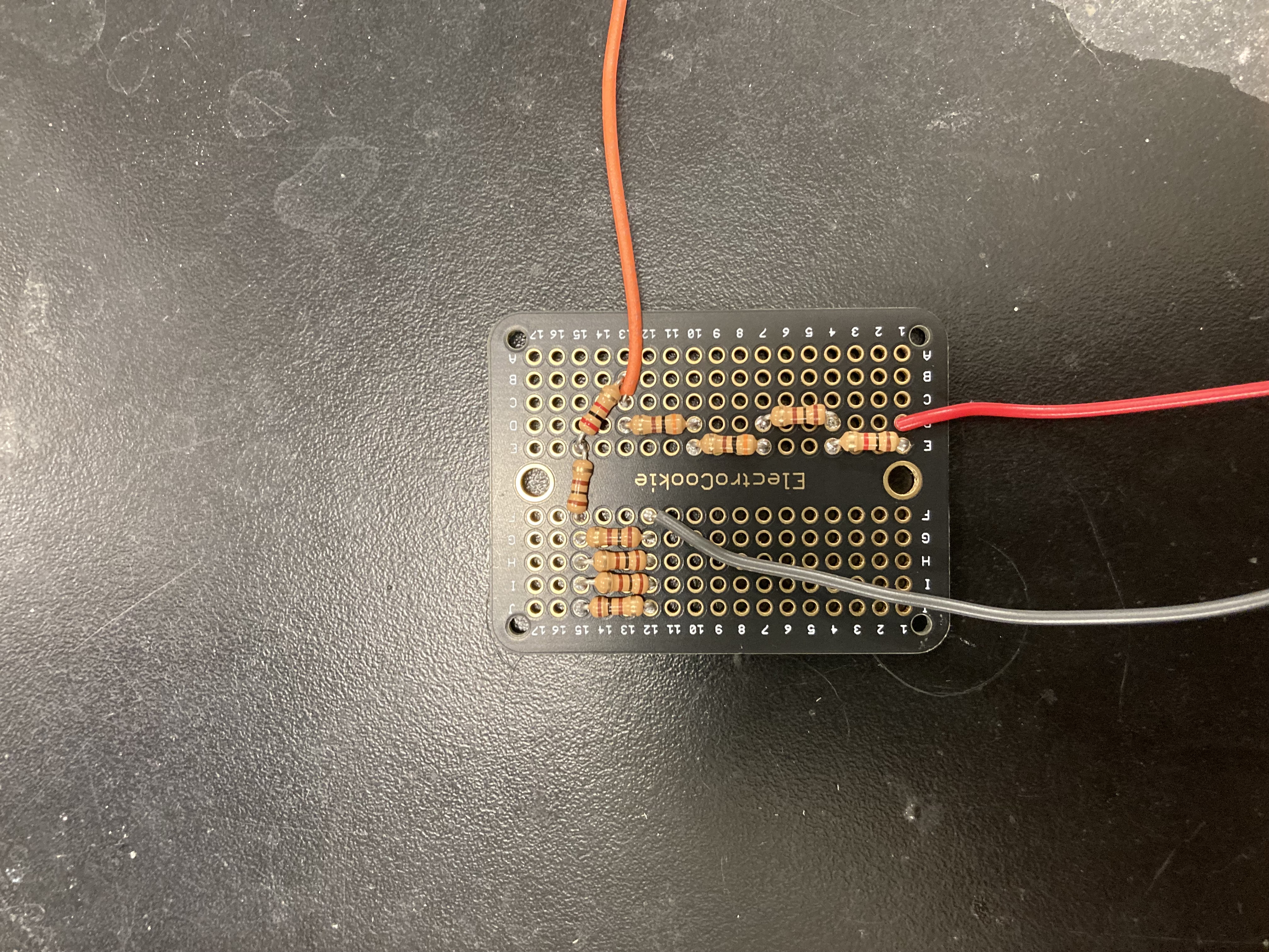
- Don't hate breadboards so much.
- Stay away from Arduino Strings and stick to char arrays. Refresh your c++!
- Design boxes while thinking of cable management and access points.
- Standard time management stuff.
- Avoid stranded wire for a while.
Next steps: surprisingly, I think not only will I be getting the pi zero back involved, but I think I will try to use only the pi zero. I think this is possible with a nice analog-to-digital converter. I might do an ESP32 instead, but I do love the simplicity of pis. I can even change the code over wifi while it stays inside the box!